Applicable Industries:
Manufacturing Plant, Food & Beverage Factory, Farms, Energy & Mining, Metallurgy, Steel Factory, Industrial Gas
Showroom Location:
None
Condition:
New
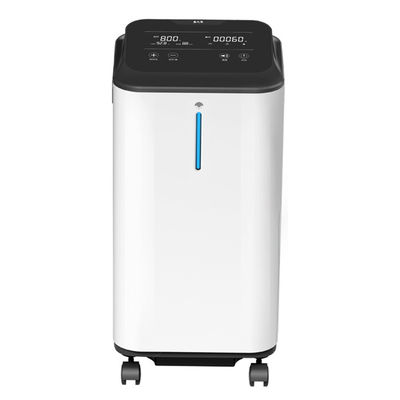
Usage:
Liquid Oxygen Nitrogen Industrial Medical Oxygen
Production Rate:
100%
Voltage:
220v/380v/6000V/50-60hz
Weight:
Actual Weight
Dimension(L*W*H):
Actual Size
Warranty:
1 Year
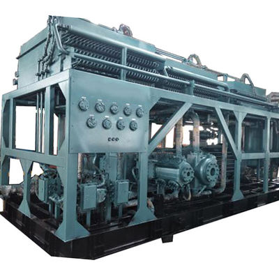
Key Selling Points:
Modular Skid Design
Marketing Type:
New Product 2020
Machinery Test Report:
Provided
Video Outgoing-inspection:
Provided
Warranty Of Core Components:
1 Year
Core Components:
Pressure Vessel, Air Purifier, Cold Box, Pre Cooler, Turbine Expander
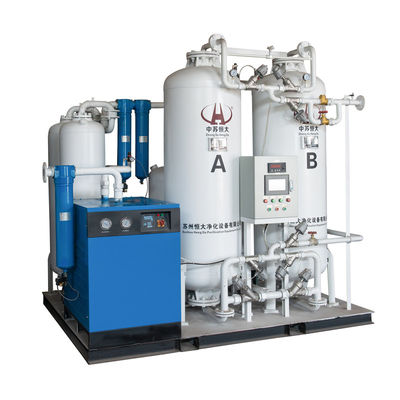
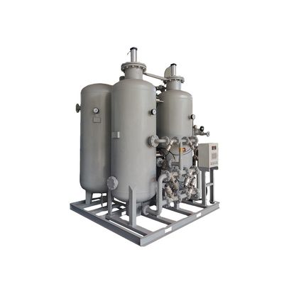
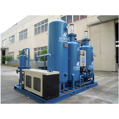
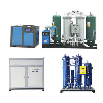
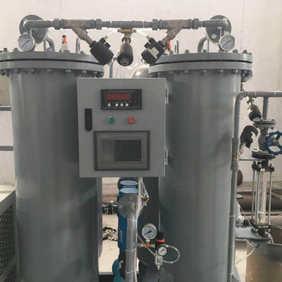
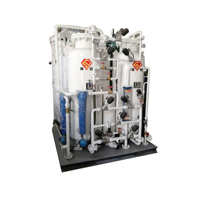
Product Name:
Small Liquid Air Separation Plant
Application:
Industrial And Medical Oxygen Nitrogen Production
Material:
Aluminum, Carbon Steel, Stainless Steel
Purity:
99.6% O2 For LOX, 10ppm O2 For LIN
Technology:
Low Pressure Cryogenic Rectifying By Turbine Expander
Type:
Skid Mounted
Capacity:
27.42 TPD
HS Code:
8419609090
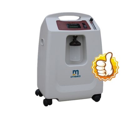
Name:
Oxygen Nitrogen Generator
Keyword:
Low Work Pressure, Turbine Expander, 13X Molecular Sieve
Local Service Location:
Egypt, India, Russia, Ukraine, Uzbekistan
After-sales Service Provided:
Video Technical Support, Free Spare Parts, Online Support, Field Installation, Commissioning And Training, Field Maintenance And Repair Service
Certification:
ISO9001:2008

 Your message must be between 20-3,000 characters!